
Robotics components · Development to production
A robotics prototype has to answer engineering questions. A production component has to carry the approved answers into every new batch.
Between those stages sit drawing reviews, fit checks, revisions, finishing decisions and repeated assembly trials. A machining partner can help by keeping those steps connected and raising manufacturing questions while the design is still open to change.
At GY Machining, we support customers developing custom robot parts and bringing approved components into production. This article explains how we work through that process, from the first model to pilot batches and repeat orders.
In this guideShow contentsHide contents
What robotics teams need from a machining partner
A robotics program can bring together mechanical designers, controls engineers, purchasing staff and assembly technicians. Each sees a different part of the problem. The designer wants the interface to work. Purchasing needs an accurate quote and a usable delivery date. The technician needs parts that assemble without an afternoon of adjustments.
Our role is to connect the manufacturing work to those decisions. We review the geometry, ask which interfaces matter, identify machining and finishing questions, and turn the approved drawing into parts that your team can evaluate. As the project develops, the inspection and manufacturing plan develop with it.
Our machining experience includes components for home robotics, medical equipment, autonomous systems and mobile robotic platforms. Across those applications, the recurring work is familiar: keep important interfaces consistent, handle design changes clearly and make the next batch to the approved definition. Customer identities and project details remain private.
That experience is most useful when it becomes a specific question about your component. Which bore locates the bearing? Which face establishes the sensor angle? Which surface must stay free from coating? We bring those questions forward while there is still time to make a practical decision.
The route from a CAD model to repeat production
We organize the conversation around the stage your project has reached. A first prototype, an assembly trial and a production release need different kinds of attention. Giving each stage a clear purpose helps both teams judge whether the next step is ready.
| Project stage | What we work on with you | Useful output |
|---|---|---|
| Drawing review | Function, interfaces, material, machining access and critical dimensions | A defined quoting basis and manufacturing questions to resolve |
| Prototype build | Approved geometry, suitable manufacturing route and priority checks | Parts and dimensional information for the planned evaluation |
| Fit and functional trial | Assembly observations, measurements and changes requested by your engineers | A controlled update to the part definition |
| Pilot batch | Repeated setup, finishing, inspection and assembly checks | Evidence that the agreed route is suitable for the next order |
| Production release | Drawing revision, process sequence, inspection scope and delivery plan | A shared manufacturing baseline |
| Repeat orders | Revision confirmation, production records, packaging and shipment identification | Parts supplied against the approved release |
The exact sequence depends on the project. Some customers arrive with a completed production drawing. Others are still choosing a bearing, motor or mounting arrangement. We start by identifying which decisions are settled and which are still being tested.
We start with the assembly, not just the outline
A STEP file shows us the solid geometry. It may not show why a feature exists, which surface establishes the assembly position or what the technician will touch first. A short explanation of the part’s function can prevent a long exchange of assumptions.
For a joint housing, we may ask for the bearing designation, mating shaft information and the relationship between the bearing seats and motor interface. For a sensor bracket, we may need the mounting datum and adjustment direction. For a gripper finger, the important information may be the contact surface and the clearance through the full opening movement.
Sharing a mating component or a section through the assembly is often helpful. You can remove unrelated confidential details and still show the interfaces that control the part. We can work under an NDA before the files are sent.
We also ask what the first batch is intended to prove. A visual packaging model, a motion prototype and an endurance-test component are different assignments. If the prototype uses a temporary material or simplified finish, identify that choice in the order so the test results are interpreted against the correct build.
Your engineering team defines the product requirements. Our manufacturing input helps make those requirements clear enough to quote, machine and inspect.
The robotics components we help manufacture
We support machined metal and engineering-plastic components used around motion, structure, sensing and assembly. The table below connects common part families with the manufacturing questions we review with your team.
| Part family | Typical features | What we review together |
|---|---|---|
| Joint and actuator housings | Bearing seats, shoulders, cover faces and mounting patterns | Fits, datum relationships and inspection access |
| Motor and gearbox flanges | Pilot diameters, bolt circles and locating faces | How the component is located and retained in the assembly |
| Links, brackets and structural plates | Thin sections, pockets, ribs and fastening points | Machining sequence, supported surfaces and assembly clearances |
| Gripper and end-effector parts | Fingers, jaws, adapters and vacuum plates | Contact geometry, weight priorities and replaceable wear features |
| Sensor and encoder mounts | Locating bores, datum faces and adjustment slots | Position, access for adjustment and repeatable mounting |
| Shafts, spacers and bushings | Turned diameters, shoulders, grooves and threads | Fit, surface condition and final assembly state |
A housing with a simple exterior can still demand careful work at its interfaces. We focus the review on the dimensions and surfaces that determine whether your assembly goes together as intended.
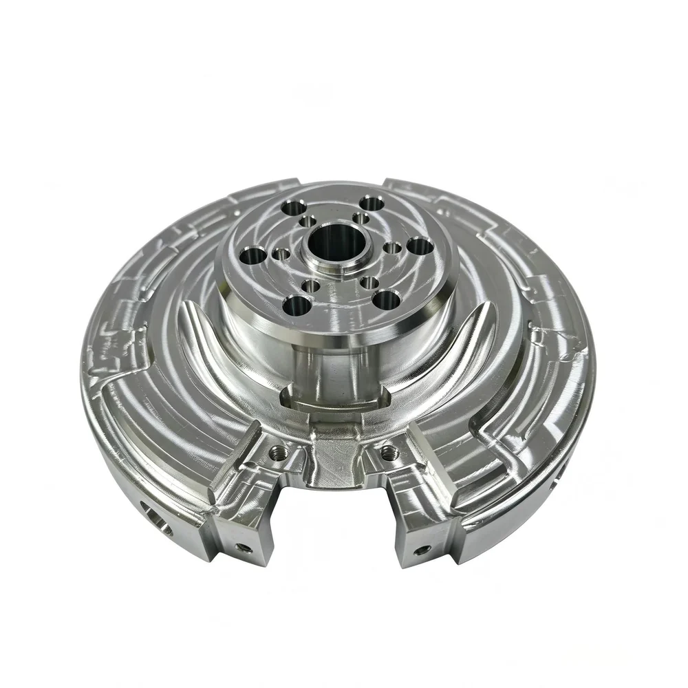
DFM: resolving manufacturing questions before cutting
Design for manufacturability is most useful when it produces a decision your engineer can act on. We examine the proposed machining route and flag features that may add setup work, delicate tooling, finishing operations or inspection difficulty.
Internal corners and tool access
We check whether a cutter can reach the required surfaces and whether an internal radius is essential to the assembly. If a mating part only needs clearance, an approved relief or a larger radius may create another manufacturing option. If the corner performs a locating function, the drawing needs to preserve that requirement.
Where EDM is appropriate for a particular feature, we explain its place in the route. A narrow through-profile and a blind recess call for different access. Our wire EDM and sinker EDM guide explains those choices in more detail.
Thin walls, deep pockets and clamping
We review how the part will be supported while it is machined and measured. A thin web between two interfaces needs a workable setup as well as a toolpath. We may discuss staged machining, a change to stock size or a different order of operations before confirming the quote.
Features on several faces
Robotics components often combine bores, slots and mounting faces in different directions. Our milling work includes 3- and 4-axis machining. We assess which features can share a setup and where another setup is necessary. The important question is how the datum relationship will be maintained through the proposed sequence.
Threads, fasteners and assembly access
We review thread callouts, hole depth and the space around fasteners. We also welcome assembly feedback about tool access or service access. A technically machinable hole can still be awkward for the person installing the screw.
What your team receives: a quotation with the relevant manufacturing questions raised early. Proposed geometry, material or tolerance changes go back to your engineer for approval before they become part of the build.
Choosing material around function and the development stage
We machine aluminium, steel, stainless steel and engineering plastics for a range of component requirements. Material selection should connect the operating environment, loading, wear, weight target, finish and procurement needs.
For an aluminium bracket or housing, we ask why the selected alloy and temper are required. A change to a higher-strength alloy should have an engineering reason. If the concern is deflection, discuss the section geometry and the stiffness requirement as well as the material designation.
For shafts, spacers and contact components, wear surfaces and the intended assembly fit deserve attention. If heat treatment or grinding is required, those operations need to be in the route from the beginning. The final inspection stage must match the required final condition.
For POM, nylon or another engineering plastic, we ask about temperature, moisture exposure, wall thickness and installed clearance. Polymer dimensions and fits need to be evaluated for the selected grade and service conditions. We avoid copying a metal-part tolerance onto a plastic component without discussing its purpose.
A development order may intentionally use a readily available material to evaluate the shape. That can be useful, provided the team records what the prototype represents. Before production, we confirm the released material and the checks needed for the actual application.
We can also discuss an approved alternative when stock availability is affecting the schedule. The alternative should be reviewed against the application rather than substituted silently. Our materials guide provides an overview of the families we machine.
The dimensions that decide whether the robot assembles
We ask customers to identify the functional interfaces instead of treating every dimension as equally demanding. This helps us plan the operations and inspection where they have the greatest value.
Bearing seats and mating diameters
The required bearing fit depends on the application, including the bearing arrangement, loading and material conditions. A nominal bore diameter alone does not define that fit. We need the specified limits or fit designation and a clear understanding of the final surface condition.
We also look at the locating shoulder and the relationship of the seat to the surrounding interfaces. A bore can be the correct size while another geometrical relationship still needs attention. The drawing should communicate those requirements separately.
Locating features and fastening features
We discuss which features establish the assembly position and which provide clamping. Locating pilots, dowels, datum faces and clearance holes do different jobs. Making that distinction explicit helps us machine and inspect the relationships that your assembly relies on.
Sensor faces and guide mounting surfaces
A sensor mount may need a controlled face or adjustment range. A guide mounting surface may require specified flatness, straightness or parallelism. Those requirements should follow the selected component’s installation instructions and the assembly design.
What your team receives: a shared interpretation of the critical features, their datums and the final inspection condition. When a requirement needs clarification, we resolve it before using it as an acceptance criterion.
Prototypes: build parts that answer the next engineering question
A prototype is valuable when the team knows what it is testing. Before machining, we ask whether the immediate goal is to check packaging, assemble the mechanism, evaluate a fit or run a functional test.
For an assembly trial, the first priorities may be the mounting pattern, pilot diameter, bearing seat and available clearances. For a weight-sensitive moving component, the prototype definition may also need the intended pocketing, wall geometry and material. The build should match the question your engineers need to answer.
We machine prototypes using the agreed drawing revision and record any approved departures, such as an omitted cosmetic finish or a temporary noncritical feature. This gives the team a clear basis for deciding what can be learned from the trial.
Before a run continues, the first article is checked against the drawing. Our inspection work uses CMM measurement alongside suitable gauges and other measuring methods. The method depends on the feature; a report is useful when it measures the requirement that actually controls the fit.
We encourage customers to plan the trial before the parts arrive. Who will assemble them? Which mating components will be available? Which measurements and observations should be recorded? A short, agreed evaluation plan helps the next revision move forward with specific information.
Instead of “the joint feels tight,” useful feedback might identify the mating part, the stage of assembly where resistance appears and the dimensions already checked. Photos, a marked drawing or a short video can make that discussion much more productive.
What your team receives: an identified build that can be connected to a drawing revision, inspection information and the purpose of the trial.
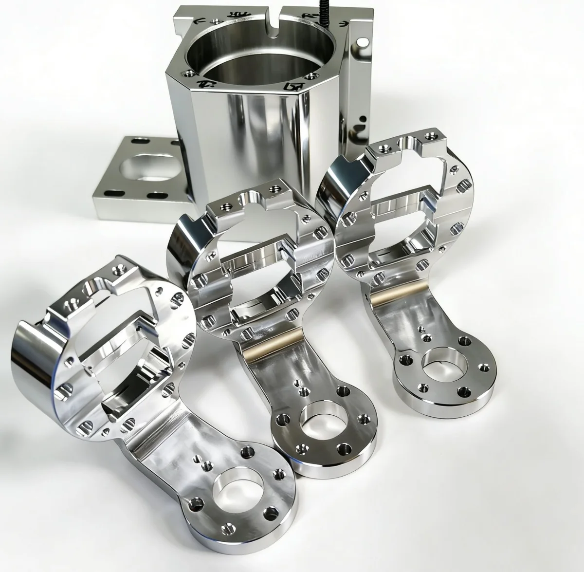
Turning test feedback into a controlled revision
Robotics development often includes several changes at once: a motor is replaced, a cable exit moves, a sensor shifts and the mounting holes follow. We help keep the machining order connected to the version your engineer actually intends to build.
For a revision, send the updated model and drawing together, identify the previous part number and revision, and describe the change. A marked comparison is particularly useful when the exterior looks almost identical.
We review whether the change affects machining access, clamping, material, surface treatment, inspection or existing work in progress. Moving a mounting hole can be straightforward. Moving the datum that controls several interfaces requires a broader check.
Before the next build, we confirm which revision applies to which quantity. If older parts are still usable for a different trial, identify that use clearly. Where rework is being considered, we assess the available material and the revised acceptance requirements before committing to it.
Your team should also identify the person authorized to approve manufacturing questions. A fast response from the wrong version of a drawing can create more delay than waiting for the correct decision.
What your team receives: a defined basis for the next build, with the change linked to the quotation, manufacturing work and inspection.
Finishing is part of the fit and the assembly plan
A robotics component may need anodising, hard anodising, plating, blasting or another specified finish. We manage finishing through the manufacturing route and discuss its effect on important surfaces before the order reaches that stage.
Coatings can change the dimensions of mating features. The drawing therefore needs to establish whether a specified bore or diameter is accepted before finishing or in the finished condition. For a critical interface, we discuss the required allowance, masking or subsequent operation with the relevant finishing process.
We ask customers to mark surfaces with special functions: bearing seats, locating pilots, electrical contact areas, sealing faces or cosmetic surfaces. The same surface-treatment instruction may not suit all of them.
Assembly trials should use the relevant final condition when the finish can affect the result. A successful fit on an unfinished prototype does not, by itself, verify the finished production interface. That is a useful question to settle before approving a batch.
Colour and appearance also need an agreed reference when they matter. State which faces are visible after assembly and where handling marks or contact marks would be unacceptable. This helps us plan protection and evaluate the finished part consistently.
What your team receives: finishing requirements connected to the functional drawing and inspection plan, rather than left as a colour note at the end of the order. See our surface-finishing options.
Pilot production: checking what a single prototype cannot show
A successful prototype is an important milestone. A pilot batch answers the next set of questions: can the agreed route be repeated, do parts assemble consistently, and are the finishing, inspection and handling requirements clear enough for the planned production order?
We use this stage to review the practical route with your team. That includes the stock, setup sequence, cutting tools, inspection points and any finishing steps that influence the final fit. Where a dedicated fixture would support repeat work, we can discuss that investment against the expected order pattern.
The customer evaluation should also repeat the assembly process across the pilot quantity. If each assembly requires a different adjustment, record where that adjustment occurs and which components are involved. Consistency needs evidence from repeated builds.
We ask whether the pilot parts are being used for engineering evaluation, internal demonstration or a production-intent build. If the acceptance criteria are different, the order and inspection plan should say so.
Before moving forward, the two teams review open issues. A drawing question, an unapproved finish sample or an unresolved mating-part change should have a clear owner. The next order is easier to plan when the unresolved decisions are visible.
What your team receives: a chance to check the repeated manufacturing and assembly route before committing to a larger release. The pilot stage is also where we can refine the recurring quotation against the actual approved job.
What we agree before releasing the production order
Production readiness means having a definition that purchasing, machining, inspection and assembly can all use. We confirm the approved drawing and model revision, material condition, finishing specification and required documentation.
We then connect those requirements to the manufacturing sequence. The quote should make clear which operations are included, where a partner process is involved and which features require particular attention. We keep the conversation tied to the actual component rather than a general statement about machine capability.
For related parts, we discuss the supply sequence. A housing, shaft, spacer and cover may need to arrive as an assembly kit. If one item has a longer material or finishing route, it should be considered in the overall schedule.
We also agree the inspection scope. The first-article checks, any in-process measurements and the final batch checks should reflect the importance of the features and the order requirements. If your project needs a specific report format or formal submission package, raise it during quotation so the scope can be assessed and agreed.
Packaging belongs in this release discussion. Identify surfaces that must be separated, parts that should be grouped and the information needed on labels. A receiving team should be able to connect the contents of a package to the purchase order and approved revision.
What your team receives: an order built around an approved manufacturing baseline, with the important details resolved before the batch is underway.
Inspection that follows the functional interfaces
Our first-article inspection is intended to confirm that the setup produces the required part before the run continues. During the order, the inspection approach should remain connected to the features that control assembly.
For a housing, that may include a bore, a locating face and a mounting pattern. For a turned component, it may be a fit diameter, shoulder position and the relationship between features. The actual plan follows your drawing and the agreed acceptance requirements.
A CMM is useful for many geometrical relationships, while suitable bore gauges, thread gauges and other instruments may be more direct for particular checks. We choose the method around the feature and its accessibility.
We can provide dimensional information showing the specified value, tolerance and measured result for the agreed checks. If a dimension must be verified after finishing, the report should reflect that stage. If an assembly condition changes the result, the measurement method should address that condition.
When your incoming inspection finds a concern, send the part number, revision, measured feature, method and result. A photograph showing the setup can help align the investigation. We can then compare the observation with the drawing and our manufacturing information.
That is how inspection becomes useful to development: it provides a common language for deciding whether to adjust the design, the process or the measurement approach. Our quality page describes the inspection resources behind this work.
Controlling cost as the design becomes stable
The first quotation and the recurring production quotation may include different work. Early builds can involve programming, setup development and additional engineering discussion. Once the design is stable, we can review the route around the expected quantities and repeat demand.
Place demanding requirements where they affect function
We ask which dimensions truly need the tight limits on the drawing. Relaxing a nonfunctional callout can create a different manufacturing or inspection option. Changing a functional fit requires engineering approval and should be evaluated with its mating component.
Review the stock and the material removed
A heavily pocketed component may begin as a much larger block. We can discuss available stock forms and the proposed machining route. If the shape is still open to change, your engineer may be able to preserve the interfaces while simplifying how the surrounding material is removed.
Consider reusable work
For a stable part family, common stock, shared tools or a suitable fixture may support repeat orders. We explain the proposed setup or tooling work so purchasing can compare its first-order cost with the expected program.
Use real order quantities
Quote the quantities you expect to buy, including the likely release sizes. An annual forecast, a purchase order for one batch and a request to hold material are different commitments. Keeping them clear helps us propose a practical supply plan.
The best cost discussions happen before the team has frozen a feature that adds little value to the finished robot. Our machining cost guide covers additional factors that influence the quote.
Keeping the next batch connected to the approved one
Once a robotics component is released, continuity becomes a central part of the job. We retain part-related manufacturing information so that a repeat enquiry can be connected to the previous work. The customer should still confirm the current part number, revision and required quantity on every order.
We check whether the new release changes material, finish, inspection or packaging. A purchase order that repeats the old part number but attaches a newer model needs clarification before machining starts.
Forecasts can help identify material or finishing requirements that deserve earlier attention. We can discuss staged shipments or a planned release pattern when it suits the order. The agreed delivery dates should distinguish dispatch from arrival and account for the actual manufacturing route.
For assembly kits, clear identification matters as much on a repeat order as on the first one. Left- and right-hand components, visually similar revisions and parts with different finishes should be distinguished in the paperwork and packaging.
If your engineering team requests a change after release, we return to a controlled revision process. We confirm what is changing and which quantity is affected. That preserves the link between the physical component and the definition your assembly team is using.
What your team receives: repeat orders managed as part of an ongoing component program, with attention to the decisions that made the earlier batch acceptable.
An example: developing a robot joint housing
Consider this illustrative workflow for a joint housing, from the first design review to a released production part.
Imagine a joint housing with two bearing seats, a motor flange, a cover and a cable opening. The first discussion establishes the bearing arrangement, the mating interfaces and the purpose of the prototype. We review the machining access and ask which relationships must be controlled from the same datums.
The prototype order identifies the approved model and drawing. Inspection checks the agreed interfaces, and the customer assembles the housing with the intended bearings, motor and mating components. The team records where assembly goes smoothly and where adjustment is needed.
Suppose the cable opening needs to move and the cover needs more tool clearance. The engineer issues a coordinated revision to the model and drawing. We review the effect on the setup, finishing and inspection, then confirm the next build against that revision.
A pilot batch evaluates repeated machining and assembly in the agreed final condition. Before production, the customer approves the released definition, and both teams agree the recurring inspection, identification and packaging requirements.
The useful result is a connected development history. The production part can be traced back to the drawing decisions and assembly observations that established its requirements.
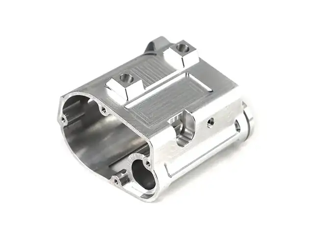
How we keep engineering and purchasing aligned
A robotics project moves more easily when technical questions and purchasing details travel together. We encourage a single enquiry package containing the model, drawing, revision, quantity, finish and required dates.
Eileen coordinates quotations and order communication, with engineering review connected to the machining work. When a question affects fit, cost or delivery, we raise the decision that needs to be made rather than leaving the teams to work from different assumptions.
For example, if a prototype is needed for a scheduled assembly trial, tell us which components are essential to that trial. If the complete part family has different routes, we can discuss the delivery plan around those priorities.
Photos and marked drawings are useful during development. A photograph can show which face is cosmetic or where a tool must reach a fastener. A marked drawing can identify the exact feature being changed. We keep formal acceptance tied to the approved requirements.
When the project reaches production, the communication becomes more structured around releases, approved revisions and shipment identification. The aim remains practical: your team should know what is being made, which decision is pending and what information is needed next.
What to send us for a robotics component enquiry
You do not need a long presentation to begin. Send the current design and enough context to identify the next decision.
- 3D model and 2D drawing: STEP or another supported model format, plus a drawing with the relevant dimensions and requirements.
- Part number and revision: identify the exact build and any earlier part we have quoted or supplied.
- Function and mating interfaces: a short explanation, assembly section or suitably limited mating model.
- Material and final condition: grade, temper or hardness, surface treatment and any surfaces to be masked.
- Critical checks: fits, datum relationships and inspection or report requirements.
- Development stage: first prototype, assembly trial, pilot batch or production release.
- Quantities and priorities: order quantity, expected repeat demand and which items are needed first.
- Dates: required dispatch or arrival date and the purpose of any scheduled trial.
If some details remain undecided, identify them. We can start with a DFM review and explain which information is needed to make the quotation and manufacturing plan more specific.
Questions robotics teams ask us
Can you help while the part is still being developed?
Yes. We can review machining access, materials, critical features, finishing and inspection questions against the current design. Your engineering team approves the product requirements and design changes.
Can we start with one or a few prototype parts?
Yes. We have no minimum order quantity. Tell us what the prototype is intended to evaluate so the build and inspection priorities match that purpose.
Can the same supplier support prototypes and production?
We support both stages. Before the production release, we review the approved revision, quantities, manufacturing route, finish and inspection requirements rather than assuming the prototype order defines everything.
Do you make complete robots?
We manufacture custom machined components for robotic systems. Send the component drawings and assembly requirements so we can assess the scope.
Can you machine housings with critical bearing fits?
We can review the housing and its specified fits. Send the bearing information, material, datums and final surface condition so we can assess the actual requirements and inspection approach.
Can you help reduce part weight?
We can review the manufacturability of your engineer’s proposed pockets, ribs and section changes. Share the weight target and functional constraints so the options can be assessed together.
Can you manufacture both metal and plastic components?
Yes. We machine a range of metals and engineering plastics. We review each grade, tolerance and service condition for the particular component.
How do you handle a revised drawing?
Send the new model and drawing together, identify the previous revision and describe the change. We review its effect on the manufacturing work, quote and inspection before the next build.
Can you provide inspection reports with the parts?
We can provide dimensional reports for the agreed checks. Tell us the required features, format and inspection stage when requesting the quotation.
Can you keep our project confidential?
We can arrange an NDA before receiving the files and discuss the information needed for the manufacturing review. We keep the discussion focused on the information your component needs for manufacturing.
Bring us the next component your team needs to prove
Whether you are preparing an early motion prototype or releasing a repeat production order, the starting point is the same: a clear part definition and a clear next step.
Developing a robotics component?
Send the model, drawing, material and quantity. Tell us what the component does and what your next build needs to prove. We will review the manufacturing questions with you.
Discuss your robotics parts →Email Eileen: 1@gymachining.comExplore our robotics machining services, CNC milling, CNC turning and inspection process.