Meta Description: Discover how iMachining can transform your CNC machining process by reducing programming and machining time. Learn about the benefits of iMachining 2D and 3D modules.
How iMachining Enhances Performance and Reduces Machining Time?
iMachining can enhance the performance of any CNC machine with any cutting tool by reducing programming and machining time. We will also explore how the iMachining technology wizard feature can automatically determine optimal feeds and speeds for first-part success.
Overview of iMachining

Thank you everyone for joining us today. We will discuss iMachining, both 2D and 3D, and its potential to increase your shop’s productivity. I will now turn off my camera for the presentation and return for the Q&A session.
Introduction to SolidCAM
iMachining is part of the productive SolidCAM suite of modules. SolidCAM is a comprehensive program; we perform CAM within SolidWorks, Inventor, and Solid Edge. We also offer the iMachining module integrated into NX CAM, providing iMachining for NX.
Our software accommodates everything from simple 2.5-axis machining to the most complex 5-axis simultaneous machining, including advanced mill-turn and Swiss-turn machines. SolidCAM introduces numerous technologies for superior tool path management.
For example, we can manage unlimited synchronization channels and axes of motion. We can execute up to five simultaneous axes, and interestingly, five simultaneous axes on two independent channels simultaneously. This is quite complex.
Focus on iMachining 2D

today we will focus on the iMachining 2D and iMachining 3D modules. Let us begin with iMachining 2D.
iMachining 2D Overview
iMachining 2D is a bulk material roughing module. It is the optimal method for material removal. It features geometry selection through feature recognition, can perform the traditional chaining method, and is accessible in 3+2. For five-axis machines requiring part orientation changes, iMachining 2D provides support.
Many part types are ideal for iMachining, including two-axis prismatic parts and three-axis mold cavity parts. While often overlooked, five-axis parts like impellers benefit from iMachining in 3+2 mode for roughing areas between vane segments. Screw machining also allows for roughing material in different indexed orientations.
Exploring iMachining 3D

many cases, iMachining for 3D is a valuable tool for updated stock analysis, which we will discuss later. iMachining’s automation strategy incorporates material information such as ultimate tensile strength and machinability. We can assign minimum and maximum cutting angles to specific materials. For the tool, we obtain cut length, number of flutes, and helical angle.
We can also assign chip thickness. Chip thickness is an intriguing parameter, which we will elaborate on later. It differs from chip load at the tool’s front and represents chip thickness at the actual cutting angle. Tool material grade influences iMachining parameters.
Geometry Considerations
Geometry considerations include shape and depth. The previously mentioned updated stock enables optimization and significant reduction or elimination of unwanted air cuts. We also account for machine kinematics, including maximum spindle speed, feed rate, and horsepower due to force-based calculations. We will delve into details shortly.
Machine rigidity is also essential. The iMachining wizard’s strength lies in combining these parameters through equations to establish necessary cutting parameters, eliminating manual calculations for the user.
Understanding Cutting Angles

To address vibration and maintain cutting angle control, we manage stepover. Unlike the common stepover term, I prefer cutting angle. Stepover differs between tool sizes. A quarter-inch tool with a 45-degree cutting angle has a different radial stepover than a half-inch tool with the same cutting angle.
Ensure tool under-engagement throughout the morphing spiral for safety and protection. Cutting angle control involves complex algorithms to prevent over-engagement and tool breakage during approach and departure. This minimizes forces on thin walls and floors, resulting in less part distortion.
Automatic Parameter Calculation

The advantage of this approach is that all parameters are calculated automatically. Users do not need to perform manual calculations; the wizard handles this process. A morphing spiral tool path is characterized by the absence of sharp corners; it maintains a tangential path. As observed, it progressively removes material.
The morphing spiral adapts to shape changes. In this instance, the morphing spiral is combined with DS slot trochoidal repositioning moves. These rapid repositioning moves maintain tool contact, preventing time loss between G1 and G0 movements. Crucially, the tool remains consistently engaged.
Handling Complex Geometries

Considering a closed pocket, the process begins with a helical approach to reach the desired depth. Subsequently, the first morphing spiral is generated, facilitating shape transitions while maintaining continuous tool engagement. This is a pivotal aspect of SolidCAM’s iMachining. The system then blends the shape to re-establish cutting angles suitable for resuming the morphing spiral.
This step is crucial for adhering to specified cutting angle ranges and maximizing morphing spiral utilization. DS slot trochoidal repositioning enables shape expansion, allowing the tool to re-engage in a morphing spiral and adapt to a new shape while optimizing chip removal efficiency.
Addressing Long, Narrow Areas
Upon completing a specific area, corner clearance commences. DS slot repositioning of morphing spirals refines corners, aligning them with the pocket geometry while preventing tool overload. Achieving this might necessitate area separation from a wall. The morphing spiral, especially in its continuous form, excels in material removal when executed correctly.
Optimizing Tool Paths
Long, narrow areas present unique challenges. Simultaneous collapse from opposite sides of the area towards the center requires varying stepovers, rendering a single continuous morph inefficient. Cutting along long sides occurs at minimum cutting angles with minimal material removal, while short sides approach or reach maximum cutting angles for optimal efficiency.
This results in an imbalanced tool path. The algorithm addresses this by automatically creating spiral efficiency separation channels, dividing the area into more symmetrical regions. Final spirals are assigned within these regions, maintaining cutting angles closer to the efficient maximum. This intelligent feature enhances overall efficiency.
Advancements in iMachining 3D

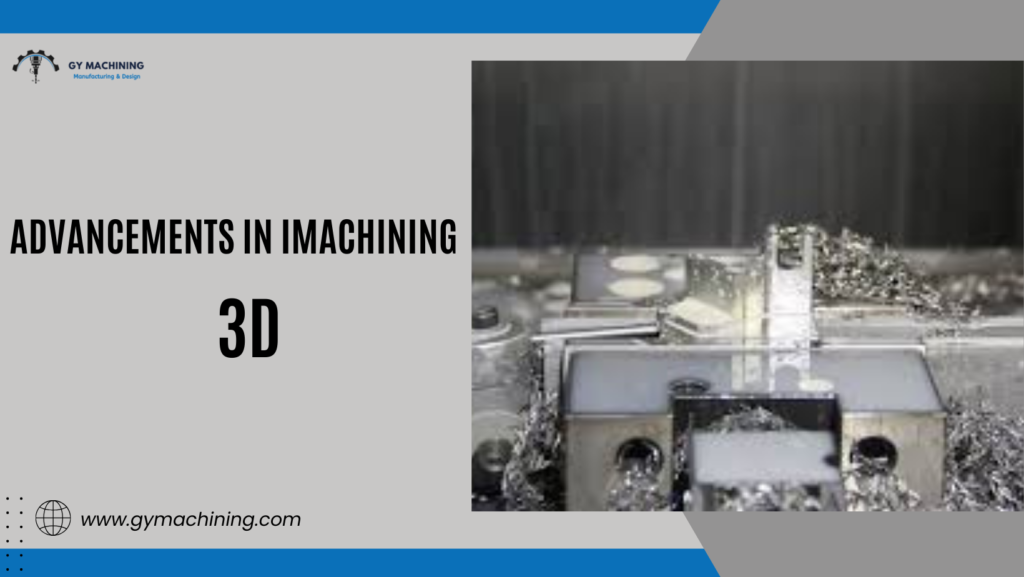
iMachining 3D introduces new dimensions to the discussion. It employs full model recognition, eliminating the need for manual chain selection and area identification. The software analyzes the entire model to determine the optimal machining strategy.
Automatic Stock Update
Automatic stock update is a powerful feature that prevents unnecessary air cuts. Scallop calculations are another key aspect. Traditionally, roughing with flat tool paths is followed by semi-finishing with a larger ball mill to address stair-stepped surfaces.
iMachining’s scallop calculations enable the specification of desired scallop heights, often achieving near-net shape accuracy directly from the roughing operation, potentially eliminating the need for semi-finishing.
Wizard Algorithms in 2D and 3D
The iMachining wizard’s algorithms function similarly in 2D and 3D, adapting to the 3D tool path or model shape. In many cases, complete part roughing is achievable in a single operation. The system incorporates rest machining to address smaller corners with smaller tools, simplifying the roughing of complex parts.
Constraint boundaries, often challenging to define, are automatically handled by iMachining 3D. While primarily associated with solid cutters, the software effectively roughs with inserted cutters as well.
Shape-Driven Step-Up Technology
We employ a shape-driven step-up technology. The concept involves taking significantly deeper initial roughing cuts with iMachining, followed by progressive depth reduction to diminish stair-stepping and achieve a near-net surface finish. This approach minimizes retracts, air cuts, and often eliminates the need for a semi-finishing operation.
Visual Demonstration of iMachining
A visual demonstration clarifies the process. Deep roughing is followed by stair-step reduction and rest material processing. While initially coarse, subsequent operations refine individual stair-steps using smaller tools to access internal corners inaccessible to larger tools. This simultaneously continues roughing, clears smaller corners, and produces a near-net finish.
Features and Benefits of iMachining
Key features include trochoidal spiral and smooth tangent tool paths integrated with minimal retracts to reduce air cuts by accurately identifying stock location. The ability to utilize the entire tool length is crucial.
Traditional pocketing often engages only a small tool tip, leading to premature wear. iMachining’s force load management enables full tool utilization, maximizing sharp flute usage.
Effectiveness with Small Diameter Tools
iMachining is particularly effective with small diameter tools and thin walls due to its physics-based force load calculations. This reduces vibration as the tool and material experience primarily rotary torsional force vectors, rather than linear ones. Consequently, tool life is extended. A forthcoming video demonstrates exceptional performance and significantly increased tool life attributed to reduced vibration and linear force vectors.
Spindle Life and Cutting Time
Spindle life also benefits from reduced vibration and load on bearings and ways. Cutting time is significantly reduced, often by over 70% in many cases, including complex or challenging materials. The physics-based approach promotes efficient chip ejection, preventing compaction and associated heat generation, thereby minimizing thermal distortion.
Case Study: West Tech Show
A recent demonstration at the West Tech show in Long Beach, California, showcased iMachining’s capabilities on a small desktop machine. A video of a dry cutting operation on 17-4 PH stainless steel at 18,000 RPM and 3/8 inch depth with a 3/16 inch tool highlights the technology. The video demonstrates consistent sound, indicating minimal vibration.
This stability arises from maintaining constant chip thickness through feed rate modulation as the cutting angle varies. The result is consistent force loads on the tool, material, and machine, preserving tool life and machine condition. Notably, the tool and part remain cool post-operation.
Conclusion
This article explains iMachining’s potential to protect tools, machines, and parts while achieving exceptional performance. This technology excels in challenging materials like jet engine hot section material, known for its extreme creep rupture strength.


